DC MOTORS DC MOTORS |
 |
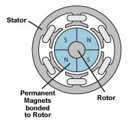
Brushed DC Motor |
 |
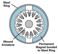
Brushless DC Motor |
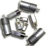
DC motors are the most common type of motors used in robotics. DC motors appear in a large variety of shapes and sizes: permanent magnet iron core, permanent magnet ironless rotor, permanent magnet brushless, wound field series connected, wound field shunt connected, wound field compound connected, variable reluctance stepper, permanent magnet stepper, and hybrid stepper motors.
Another way of DC motor characterization is brush type and brushless DC motors. This characterization refers to the manner of commutation used in motor, which converts direct current from the batteries into the alternating current required to generate motor action. If this commutation is performed mechanically with brushes, the commutator segments at the ends of the rotating rotor col physically slide against the stationary brushes that are connected to the terminals of motor. These type of motors are brush type DC motors. For brushless motors, the DC is converted into AC in the rotor electronically with position sensors and a microprocessor controller, so no brushes are needed.
Brush type motors are cheaper than brushless motors and they are more commonly used. Advantages of brushless motors over brush type are that they have reduced friction and consequently longer life and finer control for the motor, additionally the brushless motors produce less radio frequency interference. However, the brushless motors have also some disadvantages like the requirement of more extensive control circuitry to do the commutation electronically.
A conventional DC motor is formed by an arrangement of coils and magnets that creates motion from electrical power.
|
 DC Motor Components DC Motor Components |
Stator :
The stator consists of either a permanent magnet or electromagnetic windings, and generates a stationary magnetic field around the rotor which occupies the central part of the motor.
Rotor ( Armature ) :
The rotor is made up of one or more electric windings around armature arms. These electric windings generate a magnetic field when energized by the external current. The magnetic poles thus generated by this rotor field are attracted to the opposite poles generated by the stator field and repelled by the similar poles, which causes the rotor to rotate.
Commutator :
The DC motor doesnt use an external current switching device, instead it uses a mechanical connector called the commutator which is a segmented sleeve usually made of copper, mounted on the rotating shaft. The current +/- is supplied to this commutator segments with the help of brushes.
Brushes :
As the motor turns the brushes slide over the commutator segments hence creating the variable magnetic field in different arms through the commutator segments attached to the windings. Hence a dynamic magnetic field is generated in the motor when a voltage is applied across the brushes.
|
| How DC Motors Work? |
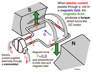 A magnetic field is produced as the current passes through the wire, or coil of wires. This magnetic field opposes against the permanent magnet set the right beside the coil A magnetic field is produced as the current passes through the wire, or coil of wires. This magnetic field opposes against the permanent magnet set the right beside the coil
Thus resulting in a force going up or down depends on the right hands rule.
When the motor rotates the direction of the current will change to the other direction. Consequently, keeping the polarity of electromagnetic force always opposing the permanent magnet. Therefore, the motor keep rotating as long as electrical power is constantly supplied.
|
| Important Properties of DC Motors |
When you want to use a DC motor in a robotic or mechatronic project, you should considered some basic properties such as direction, speed, voltage, current, power and torque.
Direction :
DC motors have mostly two terminals, across the voltage is applied. When the voltage is applied across these terminals, the motor starts to spin in one direction, and when the polarity of applied voltage is reversed the direction of the rotation is also reversed. Thus, the polarity of applied voltage determines the motor direction, while the amplitudeof voltage determines the speed of motor.
Speed :
The speed of a motor, measured in rotations per minute (rpm), depends on the applied voltage and load.
Voltage :
Each DC motor has a specified voltage that indicates the nominal voltage or the applied voltage that makes the motor run in its normal conditions. In practice, this nominal voltage is important in a project, since it indicates the maximum recommended voltage.
Current :
When a motor is powered at the nominal voltage, the current depends on the load, and increases with load. Therefore, it is important not to allow the motor to run with excessive loads that can stall it.
Power :
A motors power is the product of its voltage and current.
Torque :
Torque is defined as the product of the force times the distance from the center of the shaft of a motor.
|
| Geared DC Motors |
 DC motors usually run at too high a speed and too low a torque. In order to use these motors for robotic application, these characteristics should be improved. DC motors usually run at too high a speed and too low a torque. In order to use these motors for robotic application, these characteristics should be improved.
Gearboxes are used for this purpose. Connecting the shaft of a motor to a geartrain causes the output shaft from the geartrain to rotate much more slowly and to deliver significantly more torque than the input shaft. DC motors that have a gear box assembled to their shafts are called as gearhead DC motors, and these motor are most suitable motors for building many hobby robots.
|
References:
Mechatronic Sourcebook, Newton C. Braga, Thomson Delmar Learning |
|